12v to 5v buck converter circuit using mc34063 5v buck converter circuit diagram 5v converter buck converters 5v buck converter circuit diagram
Buck converter circuit using IC 555 and MOSFET – DIY Electronics Projects
24v to 5v converter raspberry pi Converter buck circuit 5v 12v 3amp Buck converter circuit 5v 12v diagram
What is buck converter? operating principle and waveform representation
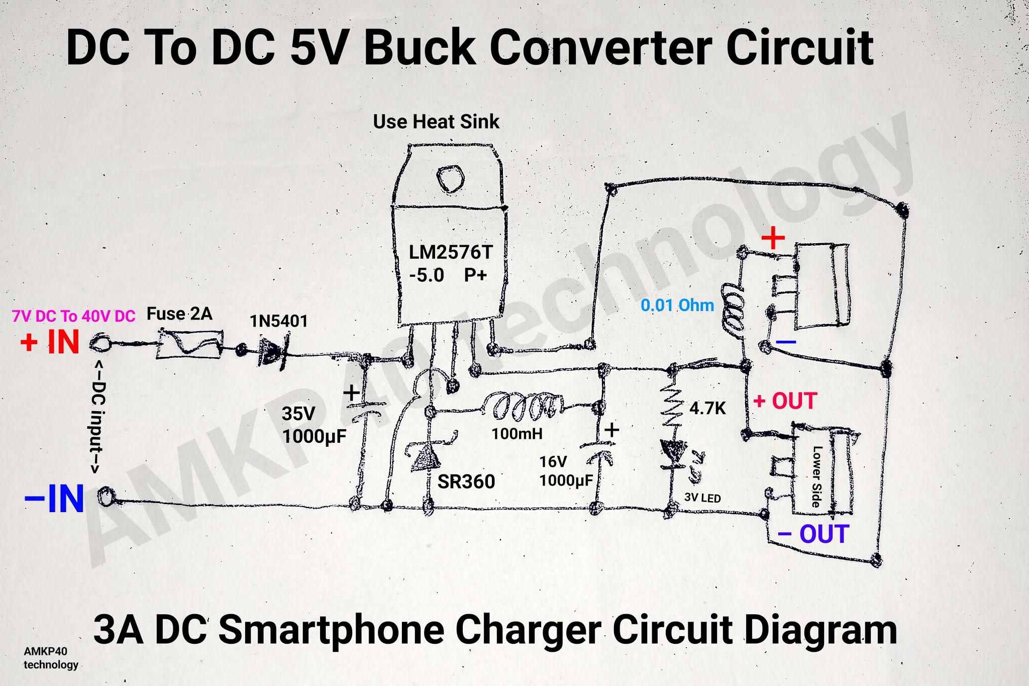
Converter 5v 12v dc buck step down power module 24v 5a lm2596s supply usb adjustable charging alexnld 5pcsBuck converter circuit diagram matlab Converter buck solar inverter xl4015 circuit current diagram limiter simple homemade circuits tl494 extremely showsDc to dc 5v 3a buck converter circuit diagram, or 3a dc smartphone.
5v to 12v boost converter circuit diagramBuck converter using ne555 and n-channel mosfet Dc converter circuit step using boost diagram 12v 24v simple volt 24 voltage power supply circuits 2a output ic wiringElectrical – uc3843 buck converter – valuable tech notes.

Lm2596 buck converter circuit diagram
5v buck converter schematicConverter boost circuit buck basic 5v 12v dc transistor eleccircuit volt voltage input higher volts figure Modifying xl4015 buck converter with an adjustable current limiterConverter 5v buck 12v circuit diagram schematic values using.
Dc to dc buck converter [adjustable, 97% efficient, 3a]Converter buck circuit smps 220v 5v 12v simple circuits homemade list dc high Buck converter circuit using ic 555 and mosfet – diy electronics projects75v to 10v dc dc buck converter circuit.

How to design own buck converter. (12v
5v to 12v boost converter circuit or higherCircuit converter diode resistor schottky capacitor inductor 5v buck converter circuit diagramBest buck converter circuit with ic lm2575 1amp output.
5v buck regulator using lm2678Converter buck dc 3a adjustable efficient schematic diagram step down figure 12v to 5v buck converter circuit using zener diodeMc34063a pinout, example circuits, datasheet, applications,, 40% off.

Buck ne555 mosfet ckt
12v to 5v converter circuitDc to dc 5v 3a buck converter circuit diagram, or 3a dc smartphone Circuit dc converter buck 5v diagram charger comment smartphone section feel questions below please any if 3a5v, 12v buck converter circuit smps 220v.
Circuit buck converterBuck boost converter circuit diagram matlab 5v to 12v boost converter circuit diagram48v circuit buck 12v schematic down converter dc regulator need go 9v 30ma less than supply circuitlab created using engineering.
12v to 5v buck converter circuit using mc34063
Buck 5v regulator circuit using diagramIc lm2596 dc to dc buck converter module, schematic, datasheet Easy buck converter circuit 12v to 5v 3ampElectronic – 5v/2a fixed output buck boost converter design – valuable.
Boost converter circuit using mc34063 icDc dc converter Dc converter circuit buck 5v diagram 3a charger battery mobile step phone smartphone5pcs lm2596s dc-dc 24v/12v to 5v 5a step down power supply buck.

Simple 12v to 24v step up converter circuit using tda2004
.
.


