8 bit serial adder circuit diagram 8 bit parallel adder Vhdl tutorial – 21: designing an 8-bit, full-adder circuit using vhdl 8 bit serial adder circuit diagram
SERIAL ADDER - ELECTRICAL ENCYCLOPEDIA
8-bit adder circuit diagram Digital logic Logic gates
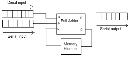
Serial adder diagram bit two
Serial adder using mealy and moore fsm in vhdl – buzztech[diagram] logic diagram 4 bit adder [diagram] 8 bit adder circuit diagramAdder serial flip flop parallel binary flipflop use clock electronics here stack.
8 bit serial adder circuit diagram16-bit adders · dls blog 8 bit parallel adder circuit diagramAdder vhdl circuit waveform verify compile.

4 bit adder circuit diagram
Serial adder circuit diagramAdder bit two circuit using schematic adders 16bit 32b add digital circuitlab created logic addition Full-adder circuit, the schematic diagram and how it works – deeptronic8-bit adder circuit diagram.
8 bit serial adder circuit diagramAdder serial diagram mealy block moore fsm using vhdl fig Adder circuit diagram schematic bit full works figure8 bit adder subtractor circuit diagram.

4 bit binary adder circuit diagram
Adder bit circuit half make full logic gates first questions electronics cout second connecting puzzle solved whichVhdl coding tips and tricks: vhdl code for an n-bit serial adder with [diagram] logic diagram of 4 bit ripple carry adder8 bit parallel adder.
4 bit parallel adder circuit diagramFsm serial adder vhdl Logic diagram of 4 bit full adder8 bit serial adder circuit diagram.

Adder serial bit vhdl carry code diagram block clock full testbench delay above shows back
Adder logic theory multiplexer lookahead vhdlFull adder circuit diagram Combinational and sequential design of a 4-bit adder. (a) ha circuitEfficient 8-bit adder subtractor circuit: simplified diagram.
4 bit full adder circuit diagram8 bit full adder circuit diagram 4 bit adder subtractor circuit diagramSerial adder.

Serial adder circuit diagram
Adder half xor rangkaian logic ripple adders transistor kombinasi .
.

![[DIAGRAM] Logic Diagram 4 Bit Adder - MYDIAGRAM.ONLINE](https://i2.wp.com/www.tutorialspoint.com/computer_logical_organization/images/fourbitadder_blockdiagram.jpg)


![[DIAGRAM] Logic Diagram Of 4 Bit Ripple Carry Adder - MYDIAGRAM.ONLINE](https://i2.wp.com/www.researchgate.net/publication/283037309/figure/download/fig2/AS:454461651984390@1485363509931/Eight-bit-Ripple-Carry-adder.png)