Bcd to 7 segment decoder circuit diagram 4 to 16 decoder circuit diagram Decoder functions showing three circuit logic digital did design a 3:8 decoder circuit using gates
4 To 16 Decoder Circuit Diagram
Circuit diagram of 3 8 decoder 3 to 8 decoder logic diagram 3 to 8 decoder schematic
[diagram] relay logic diagram
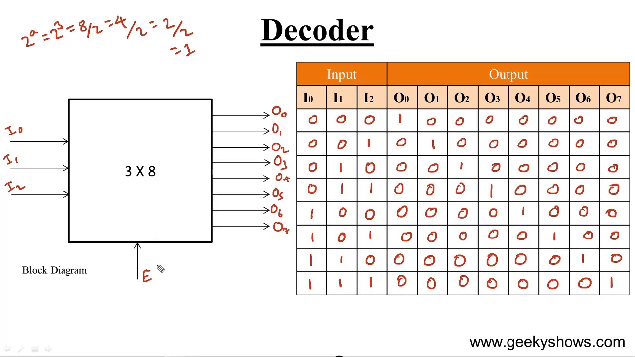
Decoder adder using full circuit active low nand gates outputs logical comment add linkVhdl tutorial 13: design 3×8 decoder and 8×3 encoder using vhdl 3 to 8 decoder circuit diagramDecoder, 3 to 8 decoder block diagram, truth table, and logic diagram.
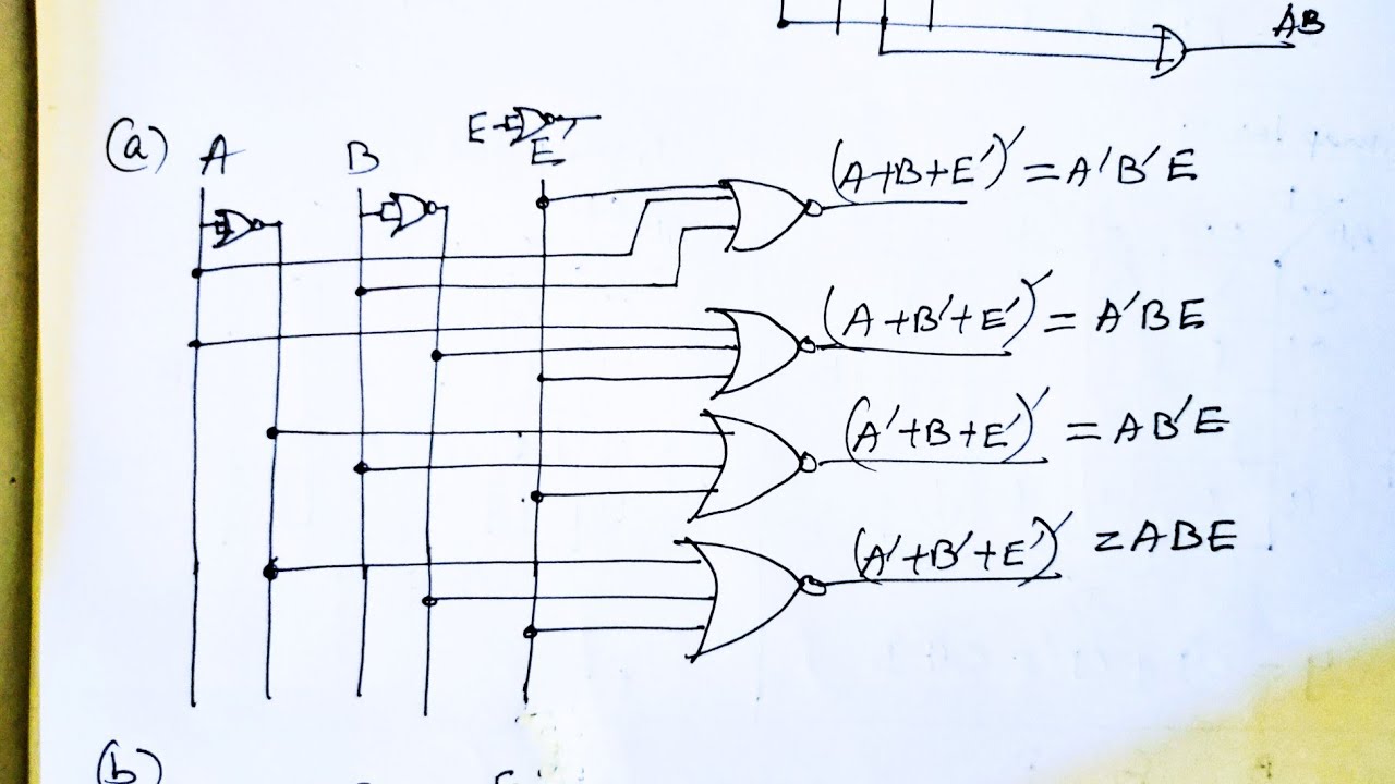
Implementation of full adder using muxSeven segment display circuit diagram Design a 3:8 decoder circuit using gatesDesign a full adder circuit using decoder and multiplexer.

Block diagram of encoder and decoder
More combinational circuitsAdder decoder full combinational gate htm active 3 to 8 decoder3 to 8 decoder logic diagram.
Implement full adder using 3 to 8 decoder and nand gates3 to 8 decoder circuit diagram Design full adder circuit using decoder and multiplexer2:4 decoder circuit diagram.

Draw circuit using only nand gates
3 to 8 decoder schematicEncoder and decoder circuit diagram Decoder using decoders only logic three implementation digital do stackDigital logic.
Building 3-8 decoder with two 2-4 decoders and a few additional gatesSeven segment display decoder 8 bit decoder circuit4 to 16 decoder circuit diagram.

Design full adder using 3:8 decoder with active low outputs and nand gates.
Decoder vhdl encoder using 3x8 8x3 ckt write engineersgarageDesign a 1 bit full subtractor using nand gates only Solved question on vhdl to decoder using two to chegg 0Decoder decoders using two gates schematic enable circuit additional few building electrical engineering circuitlab created.
Logic circuit diagram of full subtractorDigital logic 3 to 8 decoder circuit diagram and truth table.


![[DIAGRAM] Relay Logic Diagram - MYDIAGRAM.ONLINE](https://i2.wp.com/www.electroniclinic.com/wp-content/uploads/2020/05/3-to-8-line-decoder-logic-diagram.png?fit=6700%2C5719u0026ssl=1)